Category Archive: Uncategorized

Valve Product Checklist 

Erdmann Corporation will work closely with you to define your valve needs and specify the product to meet those needs. Use the list below as a guide to some of the many factors needed in making an important valve purchase. Knowing this criteria will help you select the best valve for the particular application.

Application

  • Media Being Handled, e.g., liquid, gas, slurry or solid
  • Corrosiveness of Media, e.g., pH, concentration
  • Corrosiveness of Atmosphere
  • Flow(velocity, capacity, Cv, direction
  • Pipe Size
  • Media Temperature (max-min)
  • Pressure
    • Maximum operating pressure
    • Maximum differential pressure
  • Operation,e.g., manual/automatic, on-off throttling
  • Installation Constraints
  • Envelope Dimensions
  • Weight
  • Accessibility
  • Conformance to Appropriate Standards, e.g., API, ASTM, ANSI, FM, UL, OSHA, etc.
  • Tightness of Shutoff Required 

Valve Requirements 

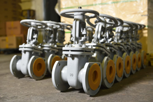
  • Type of Valve,e.g., ball, butterfly, gate, check, control, globe, plug, relief, regulator, pinch, diaphragm, etc.
  • Valve Size
  • End Connections,e.g., screwed, flanged/lugged, wafer, butt-weld, mechanical joint, etc.
  • Materials of Construction, e.g., carbon steel, resins, steel or other alloys, cast iron, etc.
    • Body
    • Trim
    • Seats
    • Bolting
  • Frequency of Operation
  • Packing (type and material)
  • Special Requirements, e.g., stem/shaft extensions, locking device, position indicator, jacketing 

Valve Actuation 

  • Type, e.g. manual, electric, pneumatic, hydraulic
  • MotionRequired
  • Rotary, e.g., quarter-turn, multi-turn
  • Linear
  • Mode of Operation
  • Double-acting
  • Spring return (spring-to-closed, spring-to-open)
  • Required Valve Operating Thrust or Torque
  • Power Supply, e.g., voltage, available air supply
  • On/Off, Throttling or Proportional Control
  • Corrosive Resistance (materials, coating, tubing)
  • Speed of Operation
  • Frequency of Operation
  • Special Requirements, e.g., tagging, testing
  • Accessories, e.g., limit switches, positioner, solenoid, valve, transducers, manual override 

Service Requirements 

  • Testing
  • Source Inspection
  • Availability of Replacement Valves, Actuators, or Parts
  • Documentation,e.g., certified prints, dimension drawings
  • Installation and Maintenance Instructions
  • Delivery Requirements, e.g., timing packaging
  • Availability of Engineering Service, e.g., application, field, factory 

Choosing the Right Valve Actuator

Valve actuators are mechanical devices that allow for remote and automatic control of valves, eliminating the need for direct human involvement. Although relatively simple in design, these devices play a vital role in the overall efficiency and safety of process systems. With the significant variability in valve and actuator designs, taking the time to research and identify an actuator that fits your system’s specific requirements is critical for ensuring a smooth and successful operation. Some of these factors include:

  • Valve Type: (manual, electric, pneumatic, hydraulic – must also be compatible with the power source.
  • Motion Required: rotary (quarter-turn or multi-turn) or linear
  • Mode of Operation: Double-acting, spring-return (spring-to-close, spring-to-open)
  • Required Value Operating Thrust or Torque
  • Power Supply: e.g., voltage, available air supply
  • On/Off, Throttling or Proportional Control
  • Corrosive Resistance: materials, coating, tubing
  • Speed of Operation
  • Frequency of Operation
  • Special Requirements: e.g., tagging, testing
  • Accessories: e.g., limit switches, positioner, solenoid, valve, transducers, manual override

Here, we discuss these several key factors and considerations that should be kept in mind during the actuator selection process.

Compatibility with Power Source

When researching valve actuator options, one of the first factors to consider is the power source. Pneumatic and electric actuators are the two most common choices for process systems. Each one has its own benefits, limitations, and requirements to consider.

  • Pneumatic actuators. Pneumatic actuators, which use pressurized air or gas to create kinetic movement, require an air supply of 40-120 psi to function. However, it is important to keep in mind that higher air pressures can be difficult to achieve, while lower pressures necessitate large-diameter pistons or diaphragms to generate the desired force.
  • Electric actuators. Electric actuators work by converting electricity to kinetic energy. Most require access to a 110-115 VAC power supply, although some are available with AC and DC motors of different sizes.

Given the various power requirements of actuators, it is important to select an option based on your available power source. For example, when no electricity source is available, pneumatic or hydraulic actuators are the most logical options. Frequency of operation and valve size should also be considered when determining which power source will be most effective for your actuator.

Temperature

Pneumatic actuators are generally tolerant of operating temperatures ranging from -4 to 174°F (-20 to 80°C), although specialized seals, bearings, and grease can extend this range to -40 to 250°F (-40 to 121°C). In low-temperature applications, it is important to be aware of the dew point as it relates to the actuator’s supply air. Condensate, which forms when temperatures fall below the dew point, can freeze within air supply lines and obstruct the flow of air to the actuator.  

Electric actuators are capable of operating in temperatures ranging from 40-150°F (-40 to 65°C). When used in outdoor applications, it is important to properly enclose the actuator to seal it against condensation, rainwater, and forms of moisture that can damage the internal components. 

Keep in mind that condensation may also enter the actuator through the power supply conduit if any moisture is present before installation. Additionally, as the motor naturally heats up and cools down during actuator operation, the resulting temperature fluctuations can create condensation. Fitting the actuator with a heater can help prevent such issues.

NEMA Guidelines

The National Electrical Manufacturer’s Association (NEMA) establishes guidelines for the manufacturing and installation of electrical equipment, including electric actuators. NEMA 7-rated enclosures can be used with electrical actuators to add explosion-proof functionality in a range of hazardous environments. Choosing an electric actuator with the NEMA 7 designation is a smart choice, especially for high-risk applications. Another option is to use pneumatic actuators, which are inherently explosion-proof due to the absence of an ignition source. Using a pneumatic actuator with electric controls is often a more cost-effective solution. 

Speed

The speed at which an actuator can perform a function is directly related to power input. Increasing the speed of a task, such as the opening or closing of a valve, requires an increase in power. Fast-acting actuators are ideal when immediate isolation or opening of a system is required, and this quick action is usually provided by pneumatic, hydraulic, or solenoid actuators. In contrast, slow-acting actuators are a better option for applications that benefit from slower, more controlled actions, such as gradually injecting cold water into a hot system.

With pneumatic actuators, the desired operating speed will determine how much airflow they require. One advantage of these actuators is that their speed can be easily controlled, usually by fitting a variable orifice such as a needle valve to the air pilot’s exhaust port. While an electric actuator’s geared motor makes speed control somewhat more difficult, it can be achieved by making adjustments to the gears. In some cases, pulsing circuits can be incorporated to enable slower operation. 

Frequency of Movement (Duty Cycle)

Frequency of operation is an important consideration since it influences the amount of stress and wear placed on the mechanical and control elements within the system. For example, isolation and regulating valves that require only occasional operation will experience significantly less wear than those that undergo near-constant or continuous operation. A more robust and resilient valve and actuator assembly should be selected in cases where continuous use is expected.

Expressed as a percentage, the duty cycle of an operation is the ratio of operating time to resting time. Pneumatic actuators exhibit a 100% duty cycle, making them well-suited for applications in which frequent valve operation is required. In comparison, most electric actuator motors only exhibit a 25% duty cycle, meaning they require frequent rest to avoid overheating. Duty cycle is less of a concern in automated on-off valves since they are ideal 95% or more of the time. 

Size

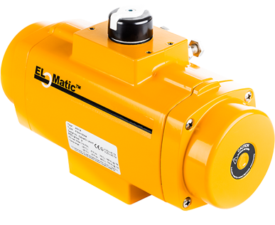
The following factors should be considered when determining the ideal actuator size for your application:

  • Valve type and torque requirements. The actuator is sized according to the specific valve being used and its calculated torque requirements. A valve’s torque requirement refers to the quantity of force needed to open or close it.
  • Minimum and maximum pressure. Pressure is another essential factor to consider when sizing an actuator for a system. It is important to test the actuator at the minimum supply pressure to make sure it can develop enough torque to function properly even at the lowest pressure point. Similarly, the valve should be able to function safely at maximum potential pressure.
  • Electricity requirements. The amount of electricity required to power the actuator will depend on its size. While large actuators generally require three-phase power suppliers, single-phase supplies are sufficient for smaller actuators. 

Safety

When selecting an actuator, make sure the device adheres to all relevant safety guidelines to mitigate the risk of explosions and other safety hazards. NEMA, CSA, and other regulatory bodies provide various ratings that indicate an actuator’s suitability for certain types of environments. 

An additional level of safety can be achieved through the use of fail-safe actuator designs. Pneumatic spring return actuators provide fail-safe capabilities by forcing the valve into a safe position if a power or signal failure occurs. Similarly, a battery backup can act as a reliable fail-safe option for electric actuators.

Valve Actuators from Erdmann Corporation

A valve actuator has a significant influence on the performance of the valve, as well as the overall system. Selecting the right actuator helps to ensure a safer and more cost-effective operation with fewer valve replacements, less downtime, and less frequent maintenance. 

At Erdmann Corporation, we take the time to understand the unique requirements and limitations of each client’s system, allowing us to provide the best possible actuator solution for the application. To learn more about our extensive actuator selection, visit our actuators page or browse our online catalog.  

Manual & Automated Valves

Erdmann Corporation

A valve is a mechanical device used to start, stop, and regulate the flow of liquids, gases, gels, powders, and other substrates by opening, shutting or partially obstructing one or more of the passageways in a piping system by way of a disc, ball or plug. This can be accomplished either manually or automatically through actuation.

Manual actuation of a valve involves direct, physical contact with its hand wheel, lever or gear operator, while power automated actuation utilizes air pressure, electricity, or hydraulic pressure controlled by flow conditions, monitoring systems, or other means that does not involve physical contact with the valve. Valve actuators may open and close valves or allow for throttling of the valve. Some valve actuators include switches or other ways to remotely indicate the position of the valve opening.

Materials of construction for valves are cast iron, carbon steel, stainless steel, chrome alloys brass, bronze, hastelloy, inconel, monel, titanium, alloy 20 and PVC among others.

End connections of valves are flanged, butt weld, threaded, socket weld, lug and wafer.

Every piping system has unique features that perform according to the purpose of its design. Understanding the five common types of valves, how they work, and their different configurations will help you select the right option for your system.


Ball Valves

Ball valves use a spherical, perforated, pivoting ball, to control on or off flow. They classify as quarter-turn valves since their operation requires only a 90-degree movement to perform their objective. The ball it uses has a hole bored through it to accommodate flow. The diameter of this hole matches the inside diameter (I.D.) of the installed pipe, allowing flow through the ball when the valve is open and closed when it is pivoted 90 degrees by the valve lever. Ball valves perform well after many cycles closing securely after long periods in one position. These qualities make them an excellent choice for shut off and control applications. There are many different seats and seals that are used in ball valves based on their service, pressure and temperature. Seat and seal materials include virgin teflon, TFM, reinforced teflon, peek, nylon, delrin, Kel F, graphite, 50-50 and metal.

Configuration Types

There are several types of ball valves, distinguished by their design:

  • Split Body
  • Single Body
  • Three-Piece Body
  • Top Entry
  • Trunnion
  • Floating

Ball valves are also classified according to their shape and function, such as:

  • Full-Port
  • Reduced-Port
  • V-Port
  • Cavity Filler
  • Multiport
  • Sanitary

Applications

Common applications of ball valves include gas processing, transmission, storage tanks, steam, high pressure, high temperature, air, liquid and other fluid applications.


Butterfly Valves


These also classify as quarter-turn valves. Butterfly valves are constructed of three main components—a disc, a stem, and a seat—and are one of the most widely used. Their simple design allows for shutting off flow by rotating the stem 90 degrees until the disc contacts the seat and completes a seal. When opened, the media flows past the disc on either side.

Configuration Types

There are two configuration types for butterfly valves, related to the location of the stem’s connection to the disc. In centric designs, the stem passes through the center of the disc, creating equal flow on either side when the valve is open. Eccentric designs include one or more stub-shafts offset from the center of the disc. Further distinctions of eccentric butterfly valves include single, double, and triple offset valves in relation to the number of stub-shafts included in their design. Typical seat and seal materials include teflon, reinforced teflon, EPDM, buna and metal among others.

Applications

Butterfly valves are common in water supply, wastewater treatment, fire protection, gas supply, chemical and oil industries, fuel handling systems, and power generation.


Gate Valves

In contrast to quarter-turn valves, gate valves do not open and close with a 90-degree rotation of the valve stem. Gate valves require multiple turns of the valve stem in either a clockwise to open (CTO) or clockwise to close (CTC) function. The turning of the valve stem raises the valve disc to open or lower it in order to close it. Gate valves are for on/off control only and should only be used fully opened or fully closed.

Configuration Types

Gate valves include the broadest range of configuration types, distinguished by the type of gate, the way they rise on the stem, and their seating configuration. Some examples include:

  • Parallel slide
  • Wedge
  • Pressure seal
  • Knife
  • Rising stem
  • Non-rising stem
  • With warm up bypass
  • Bolted bonnet
  • Welded bonnet
  • Outside screw and yoke

Applications

Gate valves are common in situations where pressure loss and free bore is among the required features, and they help to prevent damage from water hammering because they open slowly. Industrial uses of these valves include potable water, wastewater, irrigation, and gas and oil.


Diaphragm Valves


Where other valves use solid material (plug, disc, or ball) in various configurations to regulate flow, diaphragm valves use a flexible, or elastomeric, disc, which adds a pressure response element to the opening, closing, or varied control of the valve. This is a linear motion valve, actuated by pushing the diaphragm into the seat in the bottom of the valve to shut off flow or lift it to allow the flow to pass beneath.

Configuration Types

Variations in diaphragm valves relate to the different materials (butyl, teflon, EPDM, neoprene, etc.) used to make the disc, as well as connection types like threaded, compression fitted, bolt flange, clamp flange, and butt weld. They can also be plastic, rubber or glass lined.

Applications

These have minimal contact surfaces, making them the cleanest type of valve used in applications in the pharmaceutical, food processing, and water treatment industries, as well as electronics, pulp and paper, power, and high-purity water industries.


Globe Valves

Globe Valves are used for isolating and throttling flow control. Shut off is accomplished by moving the disc against the flow stream rather than across it as is the case with a gate valve. This reduces vibration, wear and abrasion. The flow pattern through a globe valve involves changes in direction, resulting a greater resistance than that in a gate valve. Valves must be installed in proper relation to media flow as indicated by a flow direction arrow on the body. These valves are available in bolted, pressure seal, welded and screwed bonnet designs.

Configuration Types

Globe valves are available with three basic types of discs: metal plug, renewable disc, and V-port. They are also available in 90 degree angle pattern and with the stem positioned in a 90 degree or 45 degree Y pattern angle to the valve.

Applications

This valve is used in boiler vents, drains; main steam vents, drains; turbine lube oil systems, seals, drains; feed water, chemical feed, fuel oil and cooling water systems.


Check Valves


Check Valves are used to prevent backflow in the pipeline. Flow is in a straight line through the valve resulting in minimum pressure drop. The disc swings or lifts into open position as media flows through the valve. Back pressure in the pipeline and/or gravity holds the disc in position. Check valves are installed in horizontal or vertical pipelines, but must be installed in proper relation to media flow as indicated by the flow direction arrow on the body. Valves are available with threaded or bolted covers and metal or renewable discs.

Configuration Types

Check valves are available in swing, piston, ball, silent, dual disc, spring loaded and stop designs.

Applications

Check valves are used in many fluid systems of chemical, industrial and power plants.

 
Manual and Automated Valves

Contact Us for Our Wide Selection of Manual & Automation Valves

Erdmann Corporation is a premier distributor of valves and automation for all industrial applications. Our services include manual valve and valve actuation expertise with an array of superior quality and high-tech products to meet the needs of our customers. Our knowledgeable and professional team with over 200 years of combined experience is driven to provide top-notch service with timely and accurate responses for each client’s specification.

Contact us to learn more about the manual and automation valve solutions we can provide to your organization or request a quote from one of our service oriented experts.


What Is An Actuator

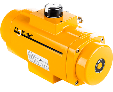
Actuators are mechanical or electromechanical devices that use a power source to drive controlled movement and positioning of industrial and mechanical equipment. While there is a wide range of actuators available, they can generally be categorized into two basic classifications:

  • Linear actuators convert energy into linear motion. They have push and pull functions that operators use for positioning. While many linear actuators are electrically powered, some are manually powered by rotational hand wheels and knobs. One example of a linear actuator is a chain wheel system, which pushes and pulls a hand wheel. These are used on gate, globe and pinch valves.
  • Rotary actuators convert energy into rotary motion. Some of the most common applications for rotary actuators include opening and closing ball valves, butterfly valves and plug valves.

Actuators find use throughout industry in a variety of mechanical applications. Manufacturers design and produce different types based on the power demands, operational environment, and size requirements of these applications, resulting in a wide selection.

Choosing the right actuator type for a particular application requires understanding both how actuators work and the differences between the various types available. The following page outlines the basic working principles behind actuators and some of the commonly used types (and their respective characteristics).

How Do Actuators Work?

Actuators connect prime movers—e.g., motors or turbines—to loads through the integration of power transmission components such as ball screws or rack and pinion arrangements. The type of motion the system produces and the type of motion the initial source provides does not have to be the same. For example, linear hydraulic cylinders can produce rotational movement through racks and pinions and a rotary actuator.

One of the most common uses for actuators is the remote operation of a valve. Different valves use different actuators based on the type of motion (and the amount of motion) needed to drive the valve open or shut. Valves use pneumatic, electric, hydraulic and several distinct manual actuators.

Actuators

Types of Actuators

Actuators are available in a number of different types with varying operating mechanisms, configurations, styles, sizes, and best use cases. Some of the common types employed in industrial applications include:

Electric Linear Actuators

Electric linear actuators convert electrical energy into distinct push and pull motions along straight lines to cause linear displacement. At their most basic, electric linear actuators consist of linear guides, drive mechanisms (such as ball or lead screws, belts, or voice coils), and motors, which work together to provide the mechanical, electromagnetic, or thermally expansive force that causes the displacement.

Many industries use these systems for applications that require precise linear positioning, such as on processing lines or in automated operations. These actuators are also suitable for use in various equipment functions such as braking machines, locking doors, and opening or closing dampers.

Electric Rotary Actuators

Electric rotary actuators convert electrical energy into rotational motion. These actuators generally consist of motors and rotary travel shaft mechanisms and, like linear actuators, are suitable for use in precision positioning and control operations. Typical applications include controlling valves, robotics, windows, and gates.

These actuators can use different motors and voice coils, depending on the specifications of the application.

Fluid Power Linear Actuators

Fluid power linear actuators convert fluid power into linear motion. They consist of cylinders and pistons that allow them to harness the power produced by hydraulic fluid, gas, or differential air pressure setups.

Multiple industries use fluid power linear actuators to control positioning systems. Automated applications, in particular, rely on precise placement and positioning of objects. These automated systems use actuators to clamp components, control welding processes, and open or close dampers and doors.

Fluid Power Rotary Actuators

Fluid power rotary actuators are actuating devices that use a cylinder, gearing, output shafts, and pistons to generate limited rotational travel. This power drives rotational movement by converting pressure from hydraulic fluid and gas into mechanical energy.

These actuators provide precise positioning and movement to facilitate the completion of automated processes. Manufacturing systems use fluid power rotary actuators to clamp parts and components, move dampers and doors, and open or adjust valves.

Some of the key considerations to keep in mind when ordering actuators include:

  • Actuator type
  • Motion required and mode of operation
  • Intended application
  • Output and mounting configurations
  • Force requirements
  • Power supply, thrust or torque
  • Rotational limitations
  • Physical space limitations and workplace safety conditions
  • Speed and frequency of operation
  • On/off, throttling or proportional control
  • Accessories, e.g., limit switches, positioner, solenoid, valve, transducers, manual override

Linear Chain Actuators

Linear chain actuators consist of sprockets (or driving gears) and chains which are used to produce fixed linear motion by pushing and pulling objects along the free ends of the chains. These actuators are available in a variety of sizes and chain styles with additional options such as chain storage compartments or straight lock attachments for rigid chains.

Facility managers can choose between many different linear chain actuators based on the following factors:

  • Actuation length
  • Chain size and type
  • Drive methods and mechanisms
  • Intended application
  • Mounting configuration

Manual Linear Actuators

Manual linear actuators consist of hand-operated components—such as gearboxes, guided linear motion mechanisms, knobs, and hand wheels—which harness the manually generated power from the rotational movement of screws and gears. Despite harnessing energy from rotation motion, these actuating devices produce linear motion.

These actuators don’t have an attached power source. Instead, they rely entirely on the manual rotational power from knobs and hand wheels to operate. Based on the load and drive force requirements, your facility may make use of different types of manual linear actuators, including variants with belt drives, lead screws, racks and pinions, and other components. Facilities typically use manual linear actuators to drive the precise motion and movement of tools, workpieces, and equipment.

Different types of manual linear actuators offer different capabilities and power. Deciding on which type is best for your application requires considering the following specifications:

  • Actuator type
  • Drive mechanism
  • Intended application
  • Travel length
  • Physical dimension limitations

Manual Rotary Actuators

Similar to manual linear actuators, manual rotary actuators use manually generated force to drive the precise movement of parts in industrial processes. However, the power output produced by harnessing the manual power input provided by knobs, levers, chain wheels, hand wheels and gear operators is rotational rather than linear.

These actuating devices are primarily used for opening, closing, and adjusting valves. Due to their ubiquity in valve applications, they are often called manual valve actuators or valve operators instead of manual rotary actuators. These actuators can drive motion for multiple varieties of valves, including ball, butterfly, check, and globe valves. In addition to their use with valves, manual rotary actuators also provide precise rotational motion for other applications and positioning.

Contact Erdmann Corp. Today

At Erdmann Corp., we provide a wide range of actuators to suit the existing valves in your facility’s system, your power output requirements, and other specifications.

To learn more about our selection of linear and rotary actuators, contact us today or request a quote to start your next order.